
Tunnel air qualityAir quality refers to the state of the air we breathe and its composition in terms of pollutants present in the atmosphere. It is considered good when poll...
Read more monitoring involves continuously measuring gases, particles, visibility and airflow conditions to protect users and workers and to control ventilation. While in road tunnels monitoring focuses mainly on traffic-related gases and particles, in railway tunnels and metro networks greater weight falls on the particles generated by braking, wheel and rail wear and resuspension.
In road tunnels, parameters such as carbon monoxide (CO)The carbon monoxide (CO) is an invisible gas (colorless and odorless) that, at the same time, is a silent killer because in just a few minutes it exhibits ...
Read more, nitric oxide (NO)Nitric oxide (NO) is one of the most important, and often underestimated, gases in the field of air quality and industrial emissions management. Colourless...
Read more, nitrogen dioxide (NO2)Nitrogen dioxide (NO2) is a harmful gas whose presence in the atmosphere is mainly due to the use of fossil fuels in combustion vehicles and industrial act...
Read more, nitrogen oxides (NOx)Nitrogen oxides (NOx) and nitrous oxide (N2O) are key air pollutantsAir pollution caused by atmospheric contaminants is one of the most critical and complex environmental problems we face today, both because of its global r...
Read more affecting air quality and climate across multiple sectors: urban, industrial and agric...
Read more and particulate matter (PM)Atmospheric particulate matter are microscopic elements suspended in the air, consisting of solid and liquid substances. They have a wide range of sizes an...
Read more make it possible to detect traffic-related pollution build-up, while real-time data helps trigger ventilation, manage congestion episodes and assess the environmental impact at the portals and surrounding areas.
Air quality has stopped being a one-off check and has become an operational data point that shapes ventilation, safety and energy consumption in the tunnel. This happens because a tunnel does not behave like an open space. It is a semi-enclosed environment where natural ventilation is limited or non-existent, traffic emissions are continuous while vehicles circulate, and congestion or an incident can send pollutant concentrations soaring within minutes, far faster than any manual ventilation system could anticipate. That is why one-off measurements are no longer enough. Only continuous data makes it possible to detect this type of increase in time and act before it compromises safety.
Throughout this article we look at why pollution behaves differently inside a tunnel than in an open space, which pollutants really matter for road tunnel air quality monitoringControlling air quality is an essential task in order to enjoy optimal environmental conditions for healthy human development and to keep the environment i...
Read more (from the historical role of CO to the growing importance of NO2 and particulate matter), and which parameters are worth measuring beyond gas concentration, such as visibility or air velocity. We will also see how a network of tunnel air quality sensorMeasuring air quality is essential for improving human and environmental health. Changes in the natural composition of the air we breathe are common in ind...
Read mores is designed and how this data is integrated with SCADA (Supervisory Control and Data Acquisition) systems to automate tunnel ventilation control, what regulations and technical standards frame these measurements, and why monitoring should not stop at the tunnel entrance, but extend to its portals and the surrounding environment to understand the real impact on nearby communities.

A tunnel is judged by what we cannot see, the air breathed by those who pass through it every day.
Why tunnel air quality monitoring is necessary
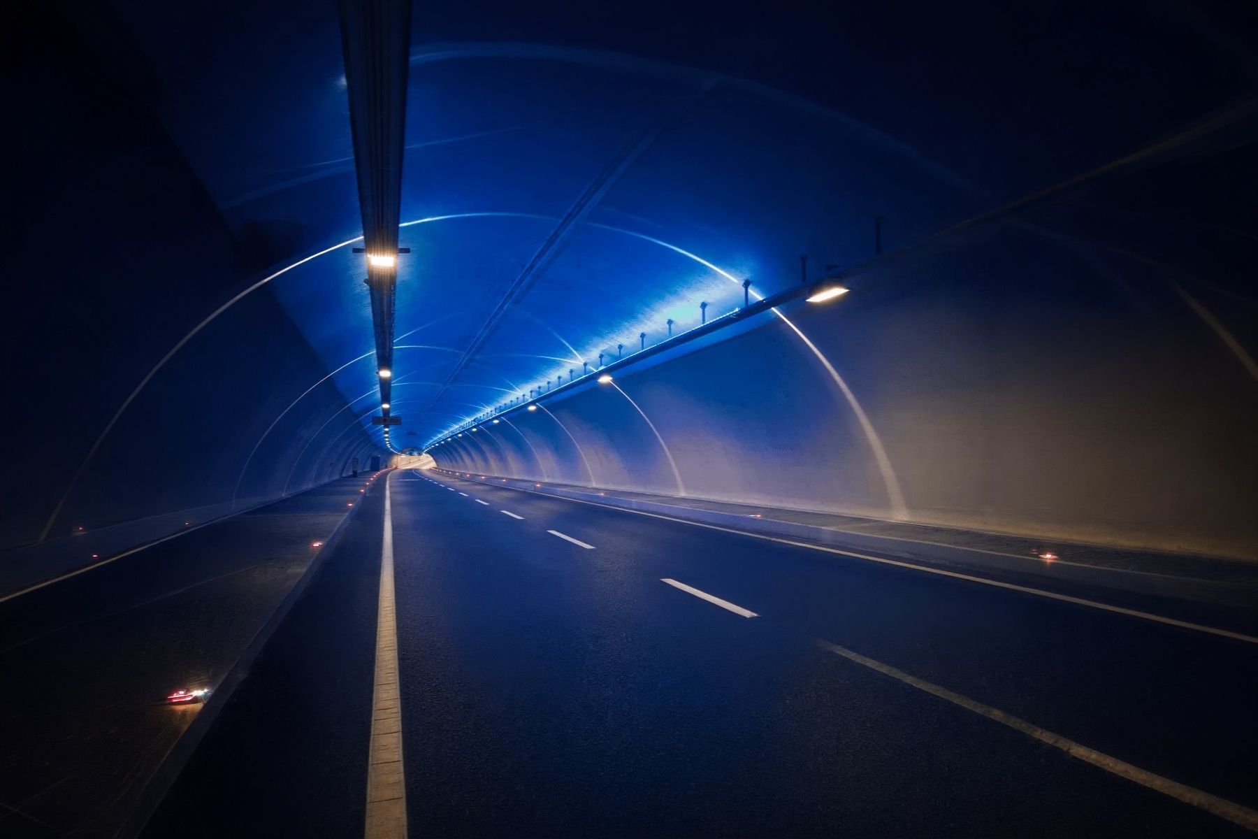
A tunnel is, above all, a different environmental exposure setting from any other stretch of road, railway line or metro network. Inside it, pollution does not disperse as easily as it does outdoors. It is shaped by the tunnel’s length and geometry, its gradients, the traffic intensity and direction, the proportion of heavy vehicles travelling through it, and whether it has natural ventilation, mechanical ventilation, or a combination of both.
Outdoor weather also plays a role, albeit indirectly. Atmospheric pressure and wind, as well as temperature at the tunnel portals, can either favour or hinder the natural inflow of fresh air, which forces mechanical ventilation systems to compensate for these variations.
Air Quality Innovation in Just 1 Click
Stay informed about the air you breathe!
Subscribe to our newsletter to receive the latest updates on environmental monitoring technology, air quality studies, and more.
Continuously monitoring these parameters serves three closely related objectives: health, safety and the tunnel’s proper operation. Air quality is an essential factor in how a tunnel functions, because it:
- Determines the exposure of those who pass through it or work in it.
- Affects visibility and the ability to react to an incident.
- Determines when and how much ventilation is needed to keep the tunnel operational without using more energy than necessary.
PIARC (the World Road Association) states precisely that a tunnel’s ventilation system must ensure adequate air quality both during the normal operation of the road facility and during maintenance work. It must also be possible to manage smoke properly should a fire break out. These three scenarios (routine traffic, maintenance and fire) call for different operational responses, and none of them can be designed in isolation. Decisions on how ventilation is configured during a tunnel’s normal operation affect the response capacity available should an emergency occur.
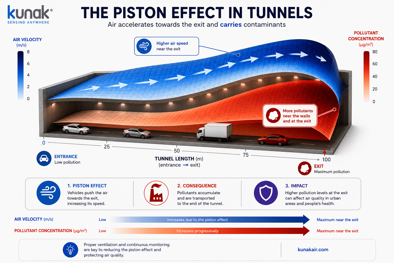
Under normal traffic conditions, vehicles travel at a speed that generates their own airflow (piston effect), which helps push pollutants towards the exit portals.
Air quality during normal traffic and congestion
The way pollutants behave in a tunnel’s air changes radically when comparing free-flowing traffic against a traffic jam inside the tunnel. Under normal traffic, vehicles travel at a speed that generates their own airflow (piston effect), which helps push pollutants towards the exit portals.
During vehicle congestion, this effect almost completely disappears because more vehicles are circulating at the same time, they stay inside the tunnel for longer, they move at much lower speeds and generate less airflow of their own, precisely when more emissions are building up in the same space. The result is an unfavourable air combination in which pollutant production increases while its capacity to disperse decreases, which can send CO, NO2 or particle concentrations soaring within a few minutes.
Studies in Chinese road tunnels attributed 26 to 40% of PM10 mass to exhaust pipe emissions, 1 to 3% to brake wear and 7 to 9% to tyre wear. Chen, X., et al. (2014).
Exposure risks for tunnel users and maintenance workers
Not all environmental exposure inside a tunnel has the same characteristics, which is why the same limits should not automatically be applied to every profile of person present in a tunnel. While a driver or passenger is exposed only for as long as it takes the vehicle to cross the tunnel, usually a few minutes even in moderate congestion, a maintenance worker, by contrast, can remain inside the tunnel for hours, often with traffic still circulating or with ventilation configured differently from usual.
A study of different occupational groups found that construction workers in Stockholm’s road tunnels had the highest exposure to NO2 and particles of all the groups analysed. Their exposure was ten times higher for NO2 and twenty times higher for elemental carbon (a diesel exhaust indicator) than outdoor workers. M. Lewné (2007).
The difference in dwell time between the profiles of people inside a tunnel means that air quality criteria applicable to brief exposures cannot be extrapolated to prolonged exposures, and that air quality monitoring must distinguish between both scenarios rather than provide a single generic value.
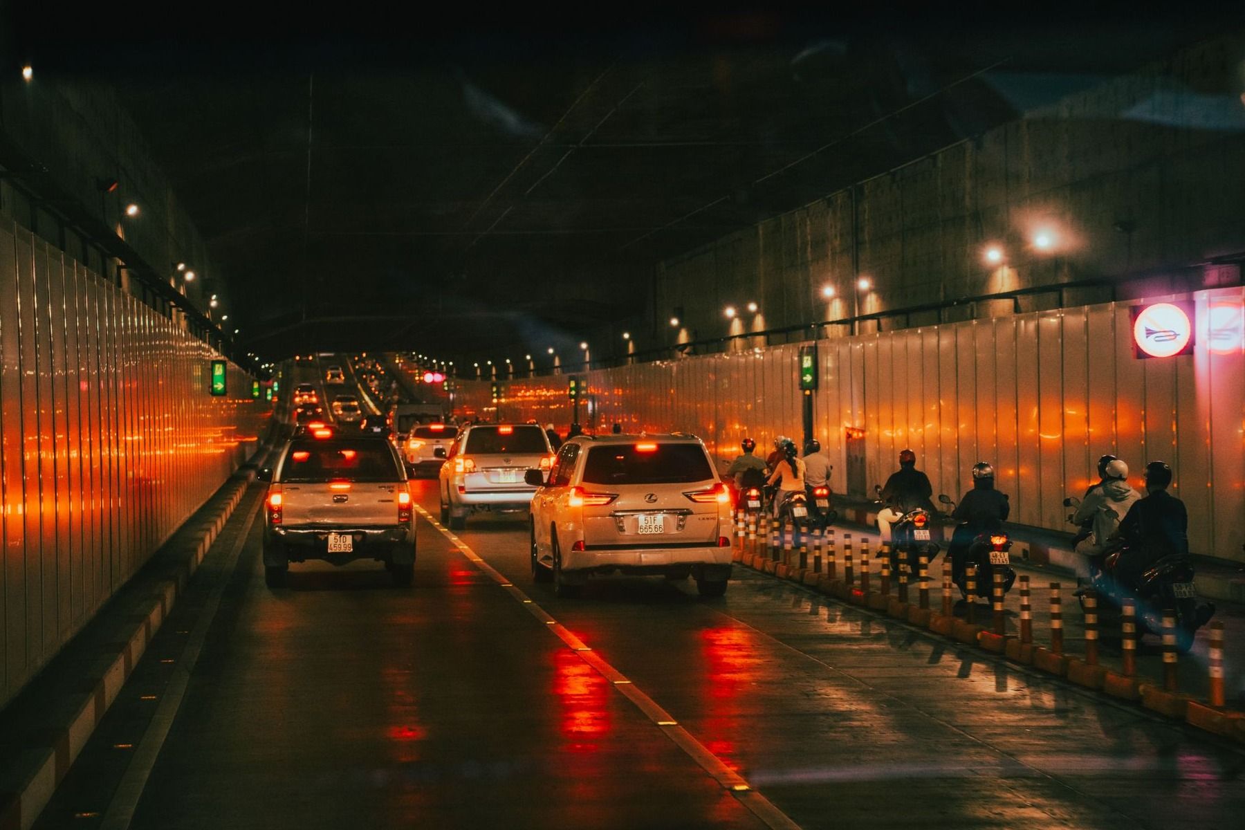
Internal combustion vehicles generate a mixture of gases and particles whose behaviour inside a tunnel depends on the source that produces them and how long they remain in a space with limited ventilation.
Main air pollutants in road tunnels
While in railway tunnels and metro networks the main air pollutants are the particles generated by braking, wheel and rail wear and resuspension, in road tunnels it is internal combustion vehicles that generate a mixture of gases and particles; their behaviour inside a tunnel depends on the source that produces them and the time they remain in a space with limited ventilation. PIARC identifies carbon monoxide (CO), particles and nitrogen oxides (NOx, the sum of NO and NO2) as the reference pollutants from internal combustion vehicles in road tunnels, precisely because they best reflect both the health risk and the need for tunnel ventilation control.
| Pollutant | Main source | Associated risk | Measurement value |
| CO (carbon monoxide) | Incomplete combustion, especially during congestion. | Acute toxicity, reduces oxygen transport in the blood. | Historical ventilation control parameter. |
| NO / NO2 (nitrogen oxides) | Combustion in diesel and petrol engines. | Respiratory irritation, with NO2 of greater health relevance. | Growing parameter in ventilation design. |
| NOx (NO + NO2) | Sum of both compounds. | Overall indicator of combustion emissions. | Regulatory and design reference. |
| PM2.5, PM10 and ultrafine particlesAt first glance, the air around us may seem clean, but beware, it hides an almost imperceptible danger: ultrafine particles (UFP). With a size so small the... Read more |
Exhaust, brakes, tyres, resuspension. | Deep penetration into the respiratory tract. | Visibility, exposure and outdoor air quality. |
| CO2 | Combustion (not toxic at usual concentrations). | Ventilation context, not a direct toxicity criterion. | Complementary indicator. |
| O2 (oxygen) | Consumed by combustion and by people. | Risk of deficiency in confined spaces. | Safety during maintenance and emergencies. |
Carbon monoxide (CO)
CO is generated by incomplete combustion, and CO monitoring in tunnels has historically been the predominant approach for sizing and controlling ventilation. Its toxicity is acute, as it reduces the blood’s capacity to carry oxygen. This is why reference manuals set limits that vary according to the traffic situation, from free flow to exceptional congestion or tunnel closure. Although per-vehicle CO emissions have fallen as emissions regulations have evolved, it remains an essential control parameter, especially in stopped-traffic scenarios where it builds up faster.
Nitrogen oxides (NO, NO2 and NOx)
NO and NO2 are generated during combustion, but their relative origin has changed over the last few decades. Exhaust after-treatment systems in diesel vehicles, such as oxidation catalysts, particulate filters and Selective Catalytic Reduction (SCR) systems, tend to markedly increase the percentage of NO2 emitted directly, to the point that in many European tunnels NO2 can account for between 20% and 30% of total NOx, depending on the proportion of diesel vehicles fitted with these technologies and the residence time of NOx in the tunnel air. This shift explains why NO2 has gained prominence over CO as a reference parameter in the most recent ventilation systems, and why NO2 monitoring in tunnels needs to track its presence directly (not just estimate it from total NOx) for more precise control.
Particulate matter (PM2.5 and PM10) and ultrafine particles
Particulate matter monitoring in tunnels shows that the particulate matter present does not come only from the exhaust pipe of combustion vehicles. As in the case of metro networks and railway tunnels, it is joined by braking, wheel and rail wear and dust resuspension; in fact these sources of particles are as relevant as combustion itself. Added to these is another origin that should not be overlooked: construction, both of the tunnel itself and of the subsequent maintenance work (wall and ceiling refurbishment, track and pavement improvements, and so on), which also generates its own particle load.
Non-exhaust emissions (brakes, tyres, road surface and resuspension) already exceed exhaust emissions in countries where diesel particulate filters have been mandatory for years.
CO2, O2 and other complementary parameters
CO2 and O2 should not be equated with the toxic pollutants above. When present at the usual concentrations in a road tunnel, they do not pose the same acute risk as CO or NO2. Their role is to provide context for other measurements, not to signal a hazard on their own.
CO2 can serve as an indirect indicator of combustion gas build-up in areas with poor air renewal, while O2 becomes especially relevant during maintenance work and in certain confined-space conditions, where a drop in oxygen levels can pose a real risk to workers.
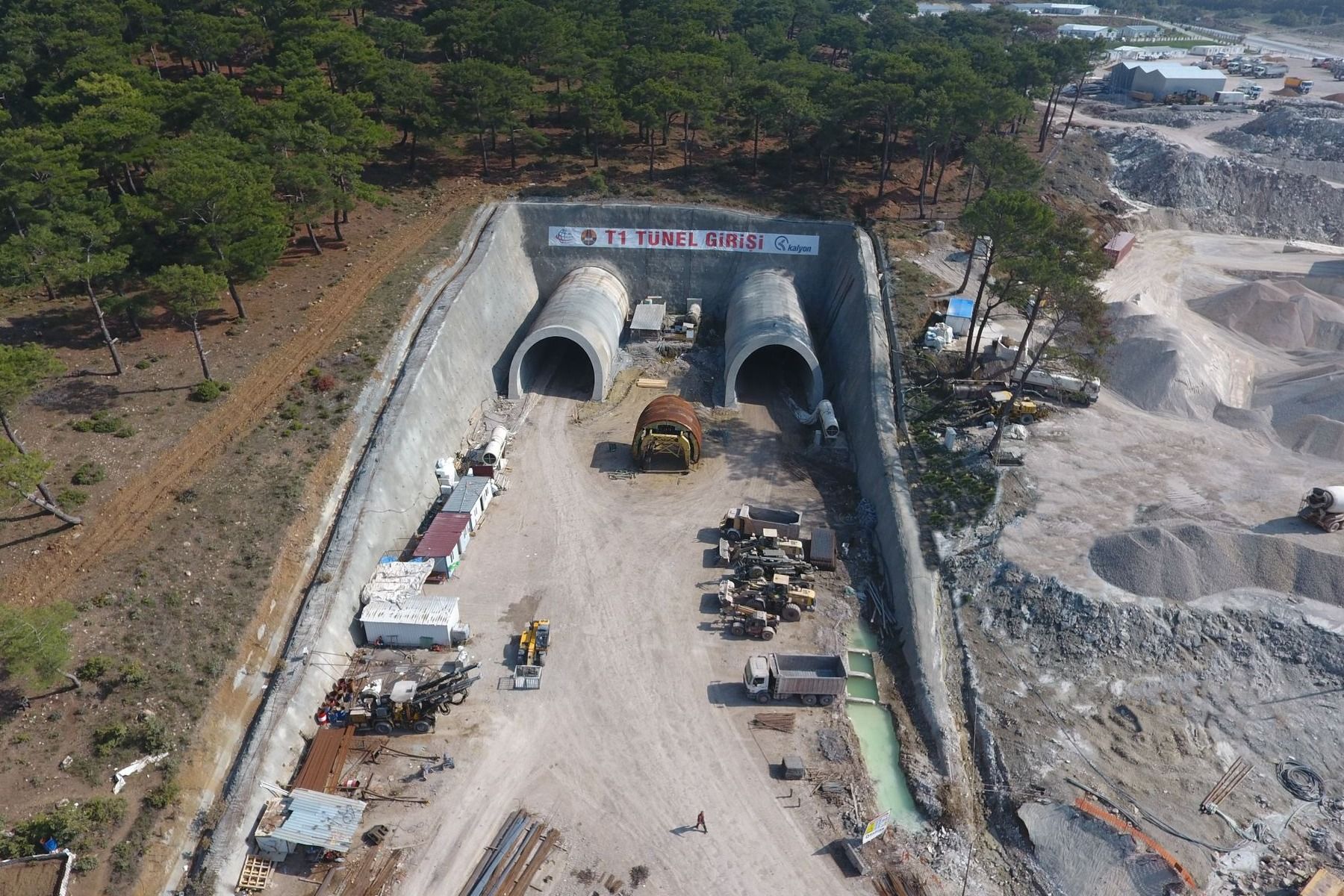
The particulate matter present in a tunnel does not come only from the exhaust pipe. Brake and tyre wear, and the resuspension of dust deposited on the road surface by the continuous passage of vehicles, are joined by construction, both of the tunnel itself and of subsequent maintenance work, which also generates its own particle load.
Air quality during tunnel construction and excavation
During a tunnel’s construction phase, the pollution profile is different and, in many respects, more intense. Excavation, drilling, blasting, earthmoving, shotcrete and the continuous use of heavy machinery generate dust, particles and gases that can build up quickly in a space with limited ventilation, usually mechanical and forced in from outside through ducts.
Dust and PM10 and PM2.5 particles
Dust monitoring in tunnels during the construction phase responds to sources very different from those of road traffic:
- Excavation and drilling at the advancing face.
- Blasting in tunnels built using the conventional method.
- Transport and loading of excavated material.
- Resuspension generated by moving machinery.
- Operation of equipment such as drilling rigs or tunnel boring machines.
Measuring PM10 and PM2.5 during tunnel construction makes it possible to assess both the dust load generated at each phase of the work and the actual exposure of workers in the areas where activity takes place.
The value of this measurement goes beyond diagnosis alone. Continuous particle data makes it possible to assess whether measures such as forced ventilation, localised extraction at the advancing face, surface watering or water misting are genuinely effective, or whether they need to be reinforced before exposure continues.
This particulate matter monitoring in tunnels logic in underground works turns dust into an operational control parameter, just as gases do once the tunnel is in service. In projects where the composition of the excavated material justifies it, it may be necessary to specifically document the presence of respirable crystalline silica.
NO2 and gases from diesel machinery
NO2 monitoring in tunnels under construction is linked, almost entirely, to the use of diesel machinery. Machines such as drilling rigs, loading shovels, material transport trucks and auxiliary equipment operate continuously in a confined space such as a tunnel. Unlike road traffic in an operational tunnel, here the emission source is more concentrated in time and space, since all the machinery tends to work close to the advancing face.
In spaces with limited air renewal, tunnel gas monitoring becomes critical, since concentrations can rise quickly if forced ventilation is not sufficient for the diesel power running at any given time.
Exposure of workers in tunnel construction involving diesel machinery has recorded NO2 concentrations that, at certain activity peaks, far exceed average exposure levels, underlining the importance of continuous control rather than one-off measurements per shift. Gren, L. et al. (2022).
Measuring NO2 continuously, as part of ongoing tunnel gas monitoring, helps detect these anomalous situations before they persist, and makes it possible to adjust the ventilation flow rate to the site’s actual conditions at each phase, rather than to a fixed estimate calculated in the project’s initial design.
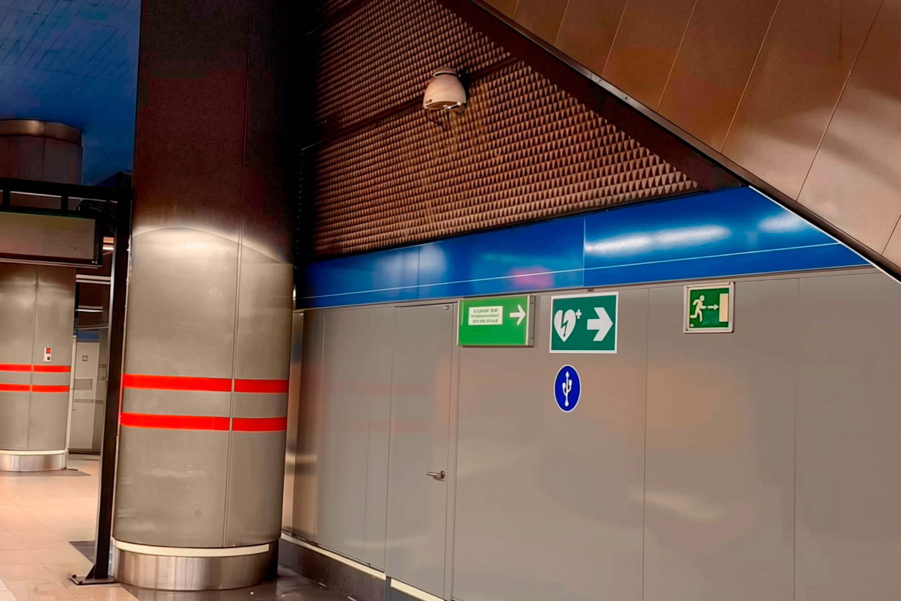
Railway tunnels and metro networks are spaces where a significant share of particles does not come from combustion engines, but from the railway system’s own operation.
Air quality in railway tunnels and metro networks
Air quality in railway tunnels and metro networks has characteristics different from those of road tunnels. These are spaces where a significant share of particles does not come from combustion engines, but from the railway system’s own operation. Contact between wheel and rail, mechanical braking, the interaction between the catenary and the pantograph, and the resuspension of deposited dust generate particulate matter that can build up in stations, platforms and underground tunnels.
Added to this internal generation are other factors that shape particle concentration, such as station geometry, tunnel depth, train frequency, their speed, the piston effect generated by their movement, and how the forced ventilation operates.
Particles generated by braking and rail wear
Mechanical braking is one of the most significant sources of particles in metro networks, especially on those stretches and at those times of day where the system cannot fully exploit regenerative braking and must rely on pads and discs as a supplement.
These emissions consist mainly of iron, together with other elements associated with rail wear such as manganese, copper, zinc, antimony, magnesium and silicon.
Contact and wear between wheel and rail is another source equal to, or more significant than braking itself. The constant friction generates particles, especially in the larger size fractions, simply through the continuous passage of trains along the tracks.
It is useful to also know when and where they are generated, how they are redistributed through the tunnel and which railway operations are associated with the highest PM levels.
PM2.5, ventilation and build-up in stations and tunnels
Particles generated in the railway environment do not necessarily stay close to the point where they are produced. The movement of trains generates a piston effect that shifts the air and redistributes pollutants along the tunnel, while forced ventilation, the infrastructure’s geometry and the distance between stations affect how they disperse.
This fraction is followed in proportion by particles that remain suspended in the air, while the share expelled outdoors through the ventilation systems is smaller.
Ventilation is not just a system for renewing the air. It also shapes the spatial distribution of particles and can directly influence the exposure of passengers and workers.
Monitoring and measures to reduce exposure
Reducing particles in metro networks is tackled through improved ventilation, cleaning of tracks and stations, adjusting speed profiles to reduce pneumatic braking, or adding particle-capture systems at source.
Beyond the specific technology used, any reduction strategy in metro stations and railway tunnels needs data to verify its effectiveness.
A network for continuous monitoring of PM2.5 and PM10, together with other environmental variables, as part of comprehensive tunnel environmental monitoring, makes it possible to:
- Detect areas with recurring particle build-up.
- Link peaks to timetables, train frequency or braking events.
- Assess the effect of ventilation and cleaning.
- Compare stations or sections with different characteristics.
- Measure the exposure of workers and passengers.
- Check the effectiveness of emission-reduction measures.
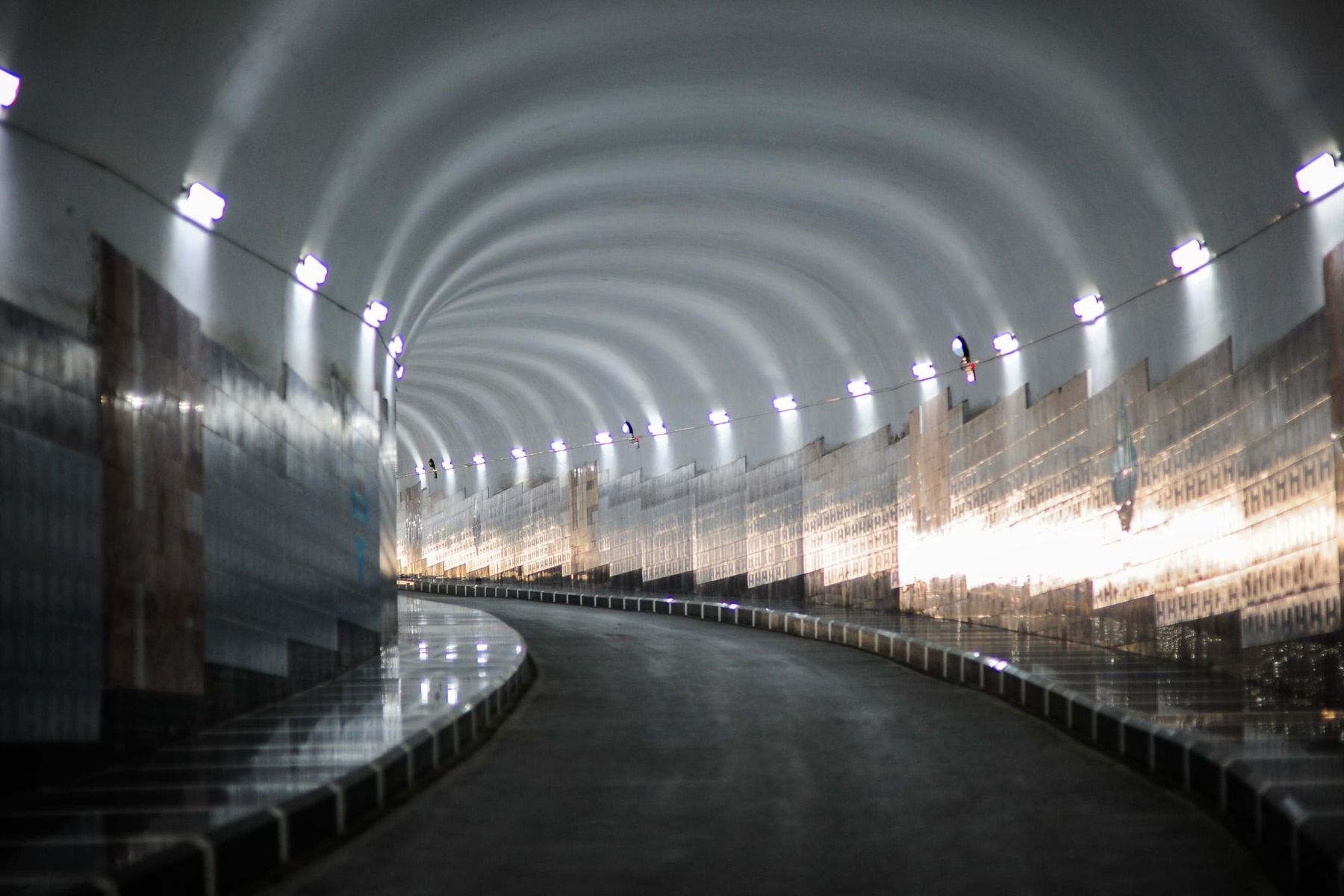
Measuring air quality in a tunnel is not driven solely by technical criteria. In many countries there is a regulatory framework that sets out what must be measured, how to do it and what safety levels must be guaranteed.
What parameters should be measured for tunnel air quality?
An air quality monitoring system suited to a tunnel, besides analysing the gases and particulate matter present, needs to know how the air moves and what visibility it offers, because both factors contribute to road safety as well as to the effectiveness of ventilation.
Gas and particulate matter concentrations
Gaseous pollutants such as CO, NO or NO2 are usually expressed in parts per million (ppm) or parts per billion (ppb), while particulate matter (PM10, PM2.5 or ultrafine particles) is measured in micrograms per cubic metre (µg/m3). This difference in units is not a minor technical detail. It reflects the fact that these are different physical magnitudes (molar concentration versus mass concentration), and that instruments capable of measuring one are not necessarily suited to the other.
Visibility and opacity monitoring
Loss of visibility inside a tunnel is directly linked to the presence of smoke and particles in the air, but measuring visibility is not the same as measuring PM2.5 or PM10 concentration for environmental purposes.
The ISO 23431:2021 standard specifies that visibility in road tunnels is measured using transmissometers (single or double path, installed at various points along the tunnel) that determine the extinction coefficient (K, in m⁻1), from which the result can be expressed as meteorological optical range or as opacity (%). The standard itself clarifies that this visibility data should not be expressed as an equivalent mass per unit volume, precisely to avoid the confusion of treating it as a PM measurement.
Air velocity and direction
This is one of the parameters that sets full monitoring apart from a simple network of gas sensors. ISO 23431:2021 specifically covers the methods for determining airflow velocity and direction in road tunnels, alongside CO, NO, NO2 and visibility, using direct-reading instruments. Knowing where the air is moving, and at what speed, makes it possible to anticipate which part of the tunnel traffic-generated pollutants are heading towards, which is essential both for sizing the day-to-day ventilation response and for managing smoke evacuation in the event of a fire. There are single-point solutions and cross-path solutions (which use ultrasonic transit time between transceivers placed on both sides of the tunnel) designed specifically for two-way or multi-lane tunnels, where airflow is not always uniform across the whole cross-section.
Temperature, humidity and other environmental parameters
Temperature, humidity and atmospheric pressure are not pollutants, but they provide essential context for correctly interpreting the rest of the data. These variables can affect the performance of certain sensors; for example, humidity can affect the response of certain electrochemical gas sensors. They also shape how the air behaves at the tunnel portals, favouring or hindering natural ventilation depending on outdoor conditions. Recording them alongside the other parameters makes it possible to tell whether a variation in air quality reflects a genuine change in emissions or simply a one-off meteorological effect.
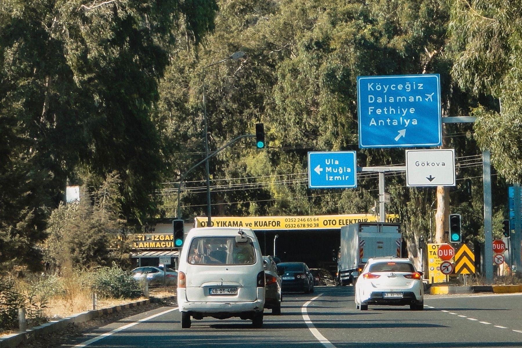
Emissions that build up inside the tunnel concentrate and escape outdoors through portals, ventilation shafts and extraction chimneys.
How tunnel air quality monitoring systems work
A tunnel air quality monitoring system is not a single sensor sending data to a screen. It is a chain that connects physical measurement to an operational decision through distributed sensors, continuous data transmission, a central system that interprets it, and a response (usually on ventilation) that is triggered from that data.
Tunnel air quality sensors and monitoring networks
Designing a network of tunnel air quality sensors is not as simple as placing a single unit and assuming it represents what happens along the tunnel’s entire length. The layout of measurement points depends on the tunnel’s length, its geometry, the number of entrances and exits, its gradients, the presence of branches, the traffic intensity, and the ventilation system’s own design.
In fact, the ISO 23431 standard does not set a universal number of instruments per tunnel, precisely because that number depends on these characteristics and on each project’s specific regulatory requirements. As a general rule, sensors tend to be placed at strategic points such as near the entrance and exit portals, at intermediate sections, and close to ventilation outlets, which are the areas where the pollution patterns most relevant for triggering an adequate and timely response tend to concentrate.
Continuous tunnel gas monitoring and real-time alerts
Continuous tunnel gas monitoring is what gives these systems their real value, not isolated one-off measurements. The basic scheme is based on:
- The sensor captures the gas or particle concentration.
- The data is transmitted to a central platform.
- The platform compares it against a predefined threshold.
- If the predefined threshold is exceeded, an action or alert is triggered.
This cycle makes it possible to react to situations such as a sudden rise in NO2, a CO spike during congestion, a loss of visibility due to smoke build-up, or even a fault in the ventilation system itself that prevents pollutants from being dispersed normally. The shorter the interval between measurement and response, the smaller the exposure margin for those inside the tunnel at that moment.
Integration with SCADA and tunnel management systems
Air quality data rarely stays within an isolated system. Its main function is to feed the central platform that manages the tunnel. In a SCADA (Supervisory Control and Data Acquisition) system, local controllers (PLCs) receive sensor readings in real time and, following pre-programmed logic, directly trigger actions such as increasing fan speed or opening extraction dampers.
The SCADA system, in turn, provides the overall picture by centralising the data from every measurement point. It displays the data on an interface for operators, which allows manual control when needed, logs the event history, and generates alerts that reach maintenance or emergency teams. This PLC-and-SCADA architecture is what allows the response to an emergency, such as a fire, to be immediate and not dependent on a human operator interpreting the data in time.
To achieve this, air quality monitoring systems such as those built around Kunak AIR Pro units fit naturally into this scheme. They measure up to five gases simultaneously (including CO, NO, NO2, SO2 or H2S) together with particulate matter. They also feature a Modbus RTU RS485 output, allowing their readings to be integrated directly into existing SCADA systems without necessarily depending on an internet connection for local data transmission. This local communication capability is relevant in a tunnel setting, where mobile network coverage can be limited or non-existent in underground sections.
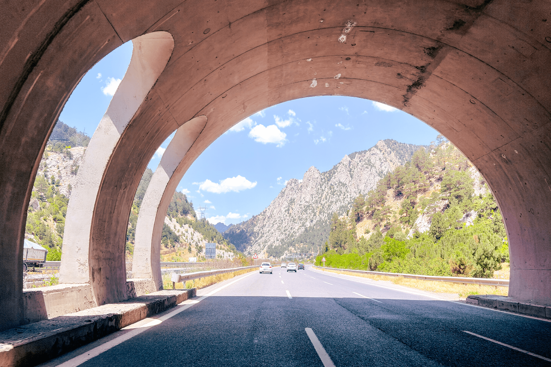
Air quality sensors in a tunnel are usually located near the entrance and exit portals.
Tunnel ventilation monitoring and air quality control
A well-designed tunnel ventilation monitoring system pursues two main objectives: controlling routine operation, supplying fresh air at a rate that is both comfortable for tunnel users and economically efficient; and, in exceptional or emergency circumstances, responding quickly and reliably to breakdowns, accidents or fires. In both situations, continuous monitoring of gases, particles and airflow, more than a passive safety exercise, acts as a management lever that does not depend on estimates or on constant manual supervision.
How air quality sensors support tunnel ventilation control
The logic behind tunnel ventilation control seems simple, even though its implementation is not. When pollutant concentration rises, the system detects the change through its sensors, ventilation responds by adjusting its intensity, and concentration returns to safe levels. But reducing this logic to a simple on/off switching of fans would oversimplify how modern tunnel ventilation systems actually work.
In practice, control systems continuously compare the measured values of CO, NOx or particles against different thresholds or states, and progressively adjust the number of active fans or their speed according to what state each pollutant is in, rather than reacting only once a limit is exceeded. When several pollutants are monitored at once, the system usually takes as its reference the one furthest from its target level at any given moment, so that the ventilation strategy always responds to the most critical variable rather than to an average that could mask a localised problem.
Ventilation efficiency, energy consumption and operating costs
Ventilating a tunnel carries a cost that goes far beyond the electricity bill. An excessive airflow rate means higher energy consumption, more fan wear, greater maintenance needs and, as a result, a higher operating cost without a proportional improvement in safety.
An insufficient flow rate, by contrast, allows pollutants to build up and compromises both safety and regulatory compliance.
A reliable, continuous measurement of air quality stops being just a matter of regulatory compliance and becomes the variable that allows ventilation to be adjusted to the tunnel’s actual conditions at any given moment, instead of operating with excessive safety margins that translate directly into higher consumption and greater equipment wear.
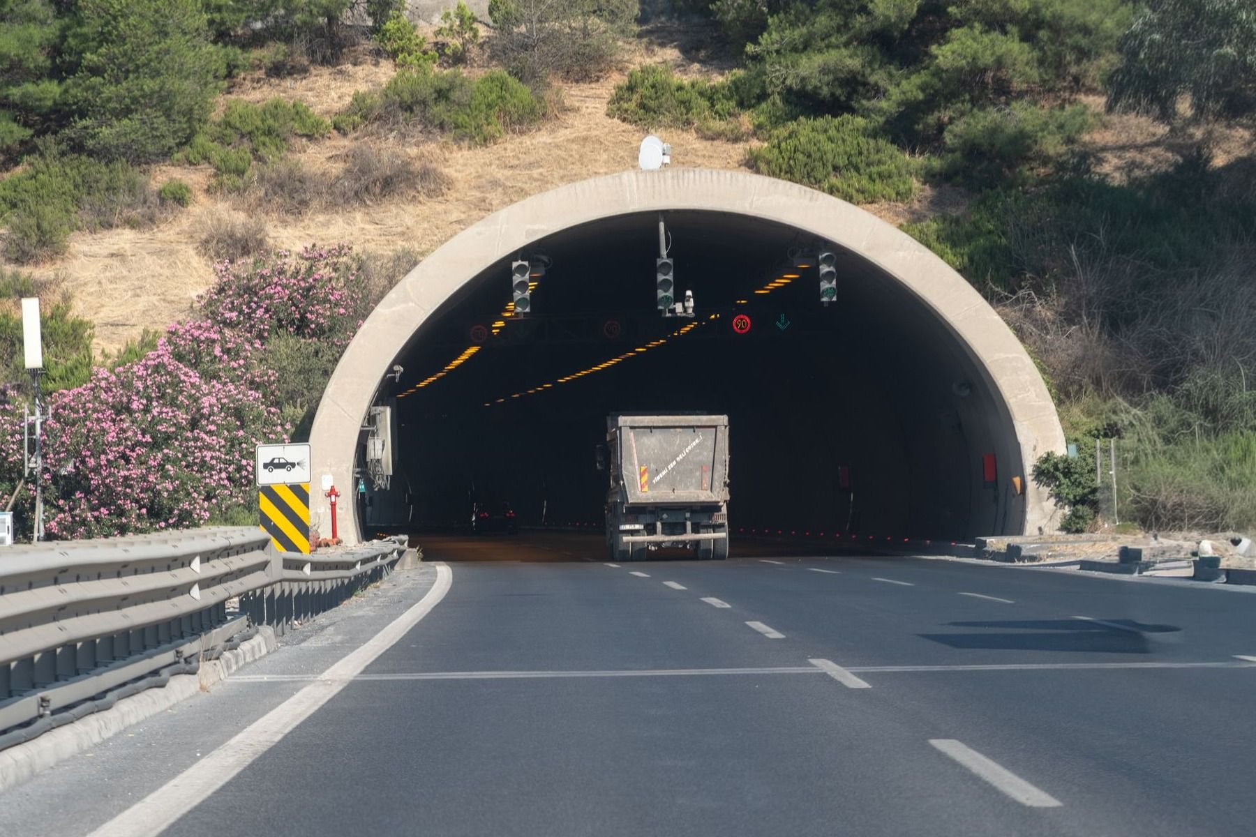
Designing a monitoring network is not about deciding how many sensors to buy, but about defining what needs to be measured, where, and with what reliability guarantees over time.
Standards and regulations for road tunnel air quality monitoring
Measuring air quality in a tunnel is not driven solely by technical criteria. Across much of Europe there is a regulatory framework setting out what must be measured, how to do it and what safety levels must be guaranteed. Knowing these references is essential both for designing a monitoring system that meets the requirements and for correctly interpreting what each standard covers and what falls outside its scope.
ISO 23431:2021 for road tunnel air quality measurement
The ISO 23431:2021, Measurement of road tunnel air quality, standard sets out specific methods for determining air velocity and direction, CO, NO and NO2 concentrations, and visibility in road tunnels, using direct-reading instruments.
European Directive 2004/54/EC on road tunnel safety
European Directive 2004/54/EC is the European framework setting out minimum safety requirements for tunnels longer than 500 metres on the Trans-European Road Network. Specifically, its section on ventilation states that a tunnel’s design, construction and operation must take into account pollutant control both during normal traffic and at peak times, as well as when vehicles are stopped due to incidents or accidents. It also sets the obligation to install mechanical ventilation in tunnels longer than 1,000 metres with a traffic volume above 2,000 vehicles per lane.
PIARC recommendations for tunnel ventilation and air quality
The World Road Association (PIARC) is the most established international technical reference for emissions, ventilation, admissible concentrations and visibility in tunnels.
Unlike ISO 23431 or Directive 2004/54/EC, PIARC does not impose a single mandatory limit; instead it publishes design and operational values that serve as a technical reference worldwide (for example, different CO thresholds depending on whether the traffic scenario is free-flowing, congested or fully stopped), and each country or administration then adapts them into its own regulations.
That is why, in practice, the NO2 limit applied in a European tunnel may not exactly match that of an Australian or Turkish tunnel, nor does the averaging time for that concentration need to be the same. This variability does not take authority away from PIARC’s recommendations; it simply reflects that factors such as tunnel length, traffic volume, or whether the exposure involves passing drivers or maintenance workers, change what is considered a safe level in each case.
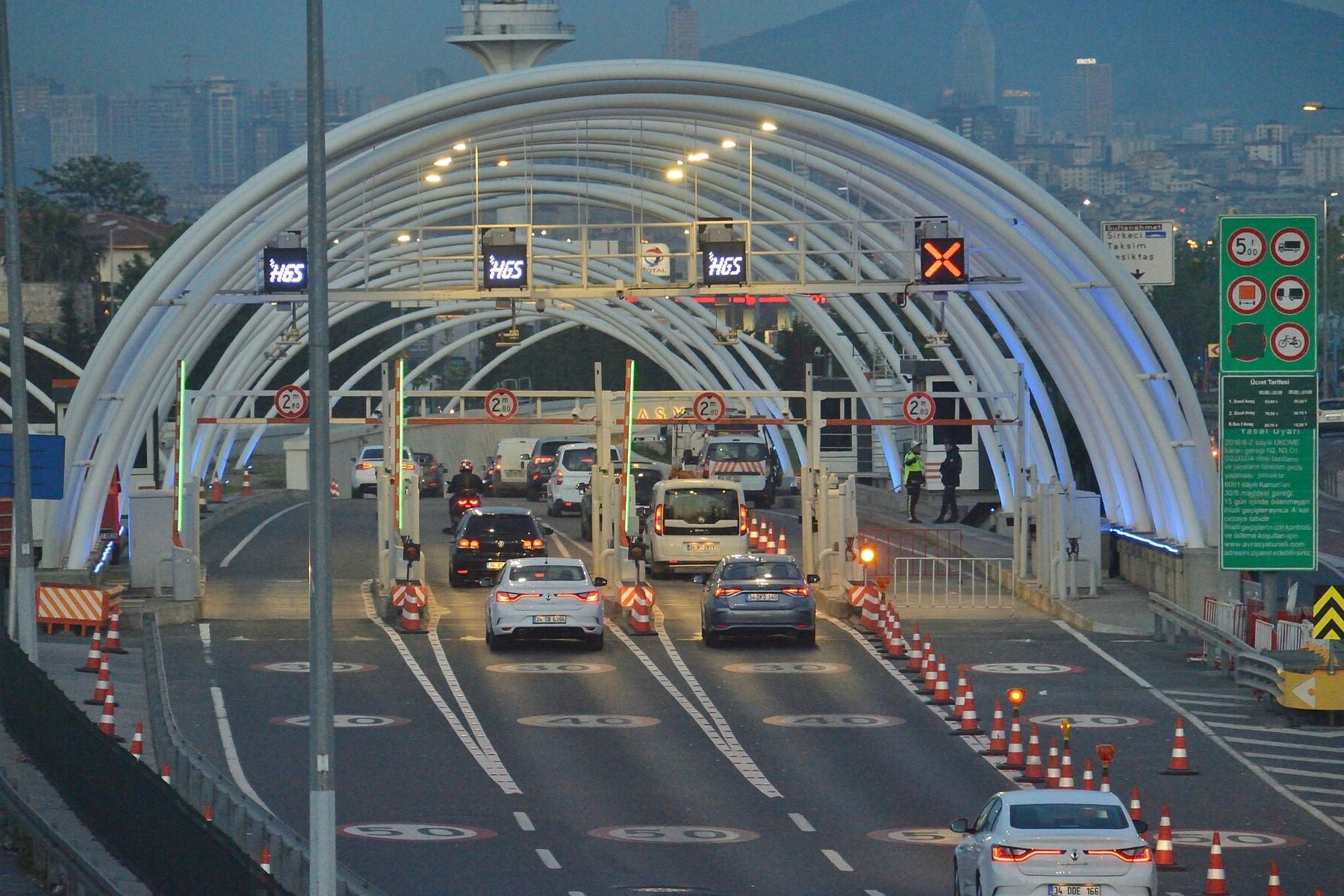
The Eurasia Tunnel, in Istanbul, incorporates six sensor clusters distributed across each level of the tunnel, in addition to outdoor monitoring stations located next to its two ventilation chimneys.
Y la parte final del artículo.
Air quality inside and outside road tunnels
Monitoring a tunnel should not stop at its access portals. Emissions generated inside do not disappear once expelled; they disperse into the surrounding environment, and understanding that outdoor impact is what distinguishes a complete monitoring approach from one limited solely to CO, NO2, visibility and fans.
Air pollution at tunnel portals and ventilation outlets
Emissions that build up inside the tunnel concentrate and escape outdoors through portals, ventilation shafts and extraction chimneys. Pollutant concentrations at portals and ventilation outlets are also relevant, as they fall off quickly from the emission point into the surrounding area depending on mechanisms such as wind speed and direction or the surrounding topography.
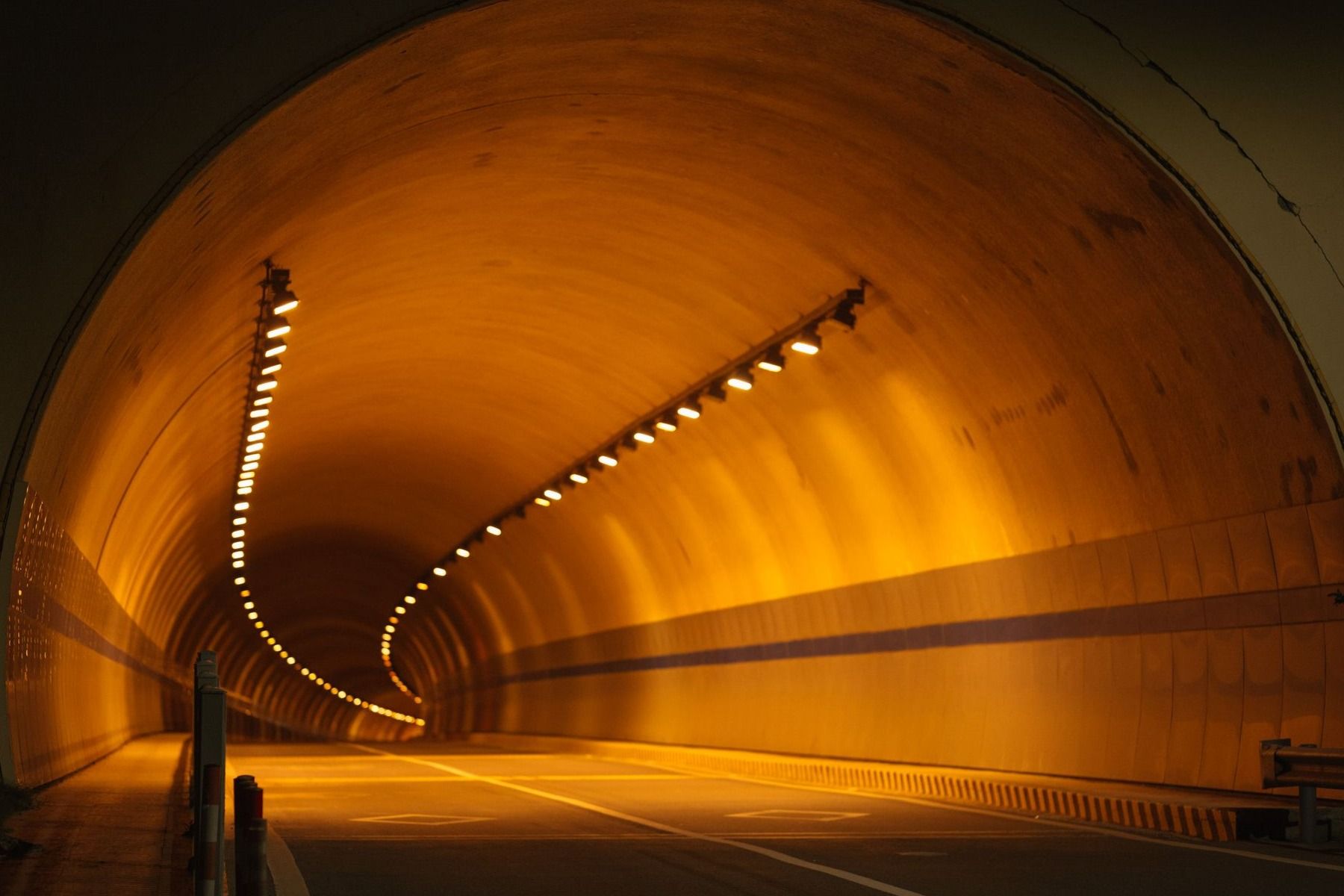
Not every road tunnel project needs to measure the same things.
Environmental monitoring around tunnel ventilation outlets
There are real projects that already combine both approaches. The Eurasia Tunnel, in Istanbul, incorporates six sensor clusters distributed across each level of the tunnel, in addition to outdoor monitoring stations located next to its two ventilation chimneys, which continuously record CO, NO2, PM10 and PM2.5.
A study covering its first two years of operation, comparing data from one year before and two years after the tunnel opened, found that average hourly CO concentrations had fallen by between 16% and 30% at stations near the ventilation chimneys, PM10 by between 44% and 46%, and PM2.5 by between 12% and 24%. NO2, by contrast, rose by between 9% and 24%, although it remained in every case below the applicable hourly standard.
Combining tunnel, traffic and meteorological data
The data obtained from monitoring networks on pollution needs to be cross-referenced with traffic and meteorological data to better interpret the origin and dispersion of pollution episodes. Without this cross-referencing, a one-off pollution spike could be wrongly attributed to traffic when it actually results from unfavourable atmospheric conditions, or vice versa.
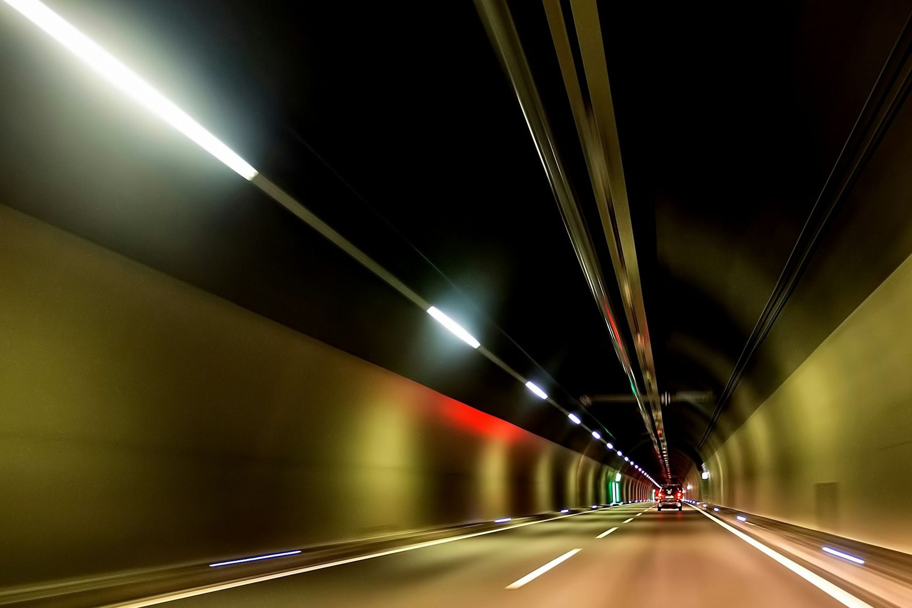
The reference pollutants in road tunnels are carbon monoxide (CO), nitrogen oxides (NO and NO2) and particles (PM10, PM2.5 and ultrafine particles),
How to design a tunnel air quality monitoring network
Designing a tunnel air quality monitoring network is not about deciding how many sensors to buy, but about defining what needs to be measured, where, and with what reliability guarantees over time. These three decisions (selection, location and maintenance) determine whether the system really fulfils its purpose or simply generates data with no operational use.
Selecting tunnel air quality sensors for each monitoring objective
Not every road tunnel project needs the same tunnel air quality sensors. A system geared towards road safety will prioritise CO, opacity and air velocity sensors; one focused on occupational exposure will need to distinguish maintenance scenarios; and one with outdoor environmental monitoring will require NO2 and PM2.5 sensors at the ventilation outlets.

The way pollutants behave in a tunnel’s air changes radically when comparing free-flowing traffic against a traffic jam inside the tunnel.
Where to install air quality sensors inside a tunnel
The location, although defined by the engineer responsible for the ventilation design, follows established patterns by setting control points near the tunnel’s entrance and exit, usually at least 100 metres inside to avoid interference from outdoor traffic, and a series of evenly spaced intermediate points, typically every 200 to 400 metres depending on local regulations.
In long tunnels with heavy traffic, some projects reduce that spacing to 170 to 200 metres to more precisely detect possible pockets of CO concentration. Mounting height also matters. Sensor heads are usually installed at around 3.5 metres, high enough to avoid splashing and direct exhaust gases, but accessible for maintenance with a standard ladder.
Data quality, calibration and sensor maintenance
A sensor that automatically triggers ventilation cannot be assessed on its purchase cost alone. This is where the concept of near-reference monitoring comes in: systems that offer traceable accuracy without the complexity or cost of a full official station. Electrochemical gas sensors (NO2, O3, CO) and optical particle counters require periodic calibration checks, comparing their readings against certified standards, since their accuracy degrades over time due to electronic drift, humidity or contamination of the sensor itself. A well-maintained system must guarantee a bounded maximum drift between checks and constant data availability, because any gap in the time series is, in practice, a blind spot in tunnel safety during that period.
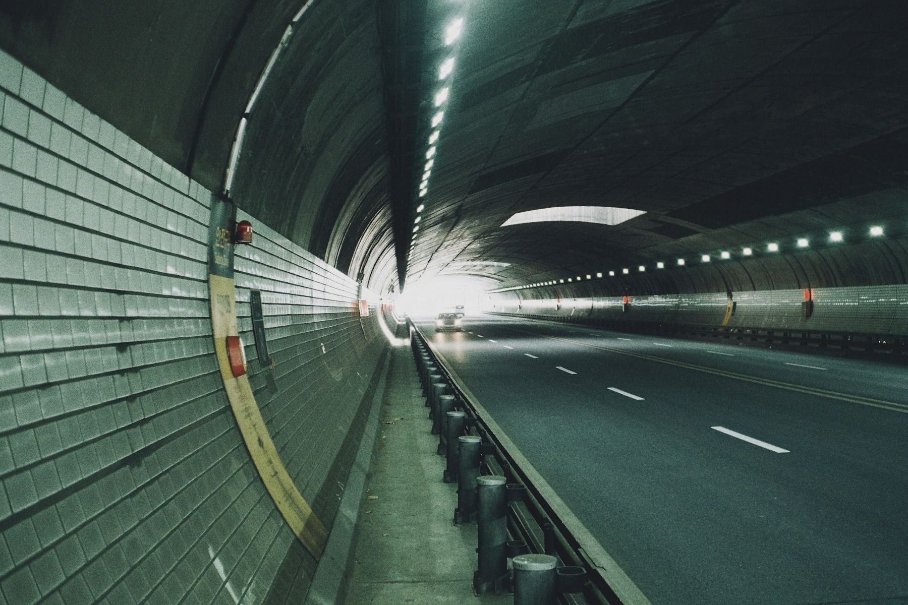
Monitoring a tunnel should not stop at its access portals. Emissions generated inside do not disappear once expelled; they disperse into the surrounding environment.
Tunnel environmental monitoring with Kunak sensors
Having a sensor network with continuous measurement of multiple environmental parameters, SCADA integration for data diagnostics, direct integration with existing control systems, and periodic remote calibration, are the requirements any tunnel environmental monitoring system must meet to suit an environment as demanding as a tunnel.
Multi-pollutant monitoring for gases and particulate matter
Kunak AIR Pro is a sensor-based multi-parameter station capable of measuring up to five gases simultaneously (including CO, NO, NO2, SO2 or H2S) together with PM1, PM2.5 and PM10 particles, as well as temperature, humidity and atmospheric pressure. Its Plug & Play interchangeable cartridge system allows the gas configuration to be adapted to each tunnel’s priority pollutants without replacing the whole unit, and allows the cartridges themselves to be replaced, minimising periods without data collection and the associated work.
Real-time data, alerts and integration with tunnel management systems
Remote calibration of zero and span values makes periodic maintenance easier without needing to move the equipment away from the measurement point. In terms of communications, it features a Modbus RS485 RTU output alongside multi-band 2G/3G/4G or Ethernet connectivity, allowing both direct integration into an existing SCADA system and data transmission to a cloud platform for real-time visualisation and alarm management.
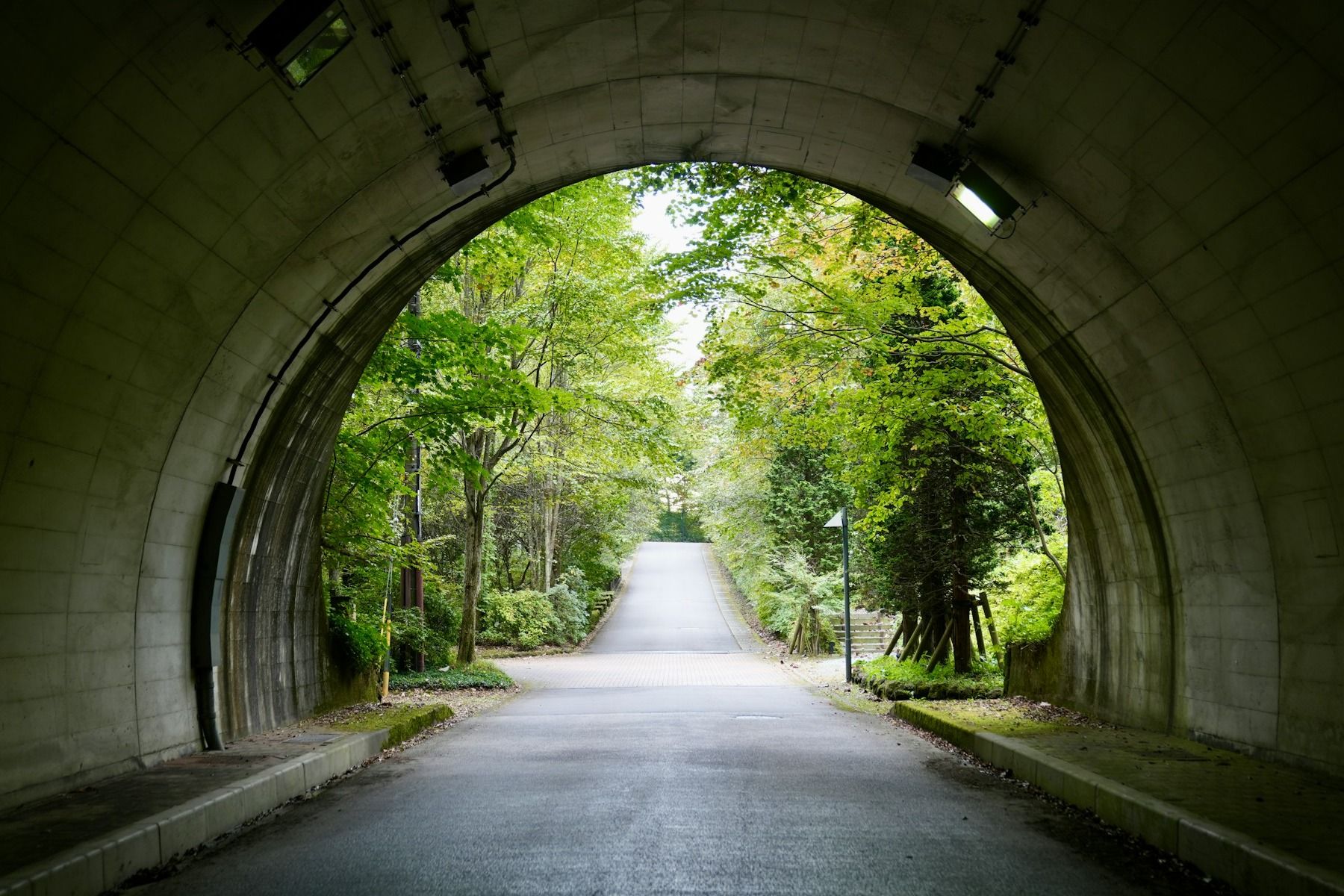
Pollution data obtained from monitoring networks needs to be cross-referenced with traffic and weather data to better interpret the origin and dispersion of pollution episodes.
Frequently asked questions about tunnel air quality monitoring
Which pollutants should be monitored in road tunnels?
The reference pollutants in road tunnels are carbon monoxide (CO), nitrogen oxides (NO and NO2) and particles (PM10, PM2.5 and ultrafine particles), according to the World Road Association (PIARC). These air pollutants are joined by complementary parameters such as CO2 and O2, which are relevant above all during maintenance work and in confined spaces. The exact combination depends on traffic, tunnel length and the regulatory requirements applicable to each project.
Why are CO and NO2 monitored in tunnels?
CO and NO2 are the toxic pollutants most directly associated with vehicle combustion inside a semi-enclosed space. CO has historically been the dominant parameter for controlling ventilation, while NO2 has gained prominence with the evolution of diesel after-treatment technologies. Both serve as direct indicators for triggering and regulating ventilation in real time.
How do air quality sensors control tunnel ventilation?
Sensors continuously measure pollutant concentration and transmit that data to a central system, usually a SCADA. When a predefined threshold is exceeded, the system automatically activates or adjusts fan speed. This response is not a simple on/off switch. Modern systems graduate ventilation intensity depending on which pollutant is closest to its limit at any given moment.
Which standards apply to tunnel air quality monitoring?
The reference standard is ISO 23431:2021, which sets out methods for measuring air velocity and direction, CO, NO, NO2 and visibility in road tunnels. At European level, Directive 2004/54/EC also sets the minimum safety and ventilation requirements for tunnels on the Trans-European Road Network longer than 500 metres, complemented by PIARC’s technical recommendations.
Where should air quality sensors be installed in a tunnel?
Sensors are usually located near the entrance and exit portals, at intermediate points spaced between 200 and 400 metres apart, and close to the ventilation outlets. The exact layout depends on the tunnel’s length, its geometry, traffic intensity and the ventilation system’s design, since ISO 23431 does not set a universal number of instruments per tunnel.

Air quality sensors in a tunnel continuously measure pollutant concentration and transmit that data to a central system, usually a SCADA.
Real-time air quality data for safer and more efficient tunnels
A tunnel is judged by what we cannot see, such as the air breathed by those who pass through it every day, without knowing whether that exposure lasts three minutes or an entire working shift. For decades, that uncertainty has been managed with one-off inspections and wide safety margins. Today, operating blind is no longer necessary.
When the concentration of CO, NO2 and particles, airflow and visibility are measured continuously, air quality stops being a box ticked during a periodic review and becomes just another operational variable of the tunnel, as live as traffic or the weather. Managers can adjust ventilation to what is actually happening inside the road tube, not to what was estimated at the design stage; detect an anomaly before it turns into a risk; and cut energy consumption without sacrificing safety.
That is the real shift: no longer asking whether the last measurement was safe, and instead knowing what is happening in the tunnel’s air at every moment. That is where continuous monitoring, backed by advanced technologies such as Kunak AIR Pro, stops being just another instrument and becomes the ally that anticipates the problem, turning a data point into a decision before the risk has a chance to materialise.
Scientific and technical references
- Gokce, H.B., Arıoğlu, E., Copty, N.K., Onay, T.T., Gun, B. (2020). Exterior air quality monitoring for the Eurasia Tunnel in Istanbul, Turkey. Sci Total Environ. 2020 Jan 10;699:134312. https://pubmed.ncbi.nlm.nih.gov/31678869/
- Lewné, M. (2007). Exposure to motor exhaust in the occupational and general environment in Stockholm county. Doctoral thesis, Karolinska Institutet. https://hdl.handle.net/10616/39992
- Lim, S., Barratt, B., Holliday, L., Griffiths, C.J., & Mudway, I.S. (2021). Characterising professional drivers’ exposure to traffic-related air pollution: Evidence for reduction strategies from in-vehicle personal exposure monitoring. Environment International, 153, 106532. https://pubmed.ncbi.nlm.nih.gov/33812042/
- Šmídová, K., et al. (2022). Concentration and inorganic elemental analysis of particulate matter in a road tunnel environment (Žilina, Slovakia): Contribution of non-exhaust sources. Frontiers in Environmental Science. https://www.frontiersin.org/journals/environmental-science/articles/10.3389/fenvs.2022.952577/full
- Wei, X., Li, S., Wang, X. et al. (2026). The optimization study of the operational ventilation system for long tunnels on secondary highways. Sci Rep 16, 2860. https://www.nature.com/articles/s41598-025-31830-4#citeas
- Gren, L., Krais, A.M., Assarsson, E., Broberg, K., Engfeldt, M., Lindh, C., Strandberg, B., Pagels, J., Hedmer, M. (2022). Underground emissions and miners’ personal exposure to diesel and renewable diesel exhaust in a Swedish iron ore mine. Int Arch Occup Environ Health. 2022 Aug;95(6):1369-1388. https://pmc.ncbi.nlm.nih.gov/articles/PMC9273542/
- Liu, J., Shi, Z., Wang, Y., Zeng, J., & Ji, W. (2026). Particulate matter across subway microenvironments worldwide: A systematic review and quantitative health-risk assessment. Journal of Hazardous Materials, 512, 142311. https://pubmed.ncbi.nlm.nih.gov/42102562/