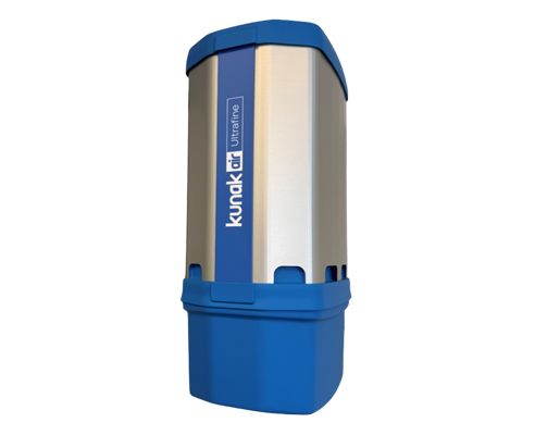
UFP sensor
Ultrafine particles
Reliable real-time
information on UFP
ELECTROSTATIC TECHNOLOGY | NON-COLLECTIVE DESIGN

Where are they found?
Ultrafine particles (UFPs), with a diameter of less than 0.1 μm, originate mainly from anthropogenic sources such as vehicle combustion, industrial processes, domestic heating and biomass burning.
These particles are present in urban and industrial environments, as well as in areas close to roads and production plants. Natural sources also contribute, although to a lesser extent since most UFPs originate from human activities that generate complex emissions and secondary pollutants in the atmosphere.
Why measure them?
Ultrafine particles are among the most hazardous pollutants for human health due to their ability to penetrate deep into the lungs and reach the bloodstream. Their size and composition make them highly reactive, capable of causing inflammation, oxidative stress and damage to vital organs.
Measuring them is crucial for risk assessment, the design of effective policies, and the protection of vulnerable populations, particularly in urban and industrial settings where their concentration tends to be higher.
UFP sensor
The UFP sensor employs advanced technology based on electrical charging and electrostatic detection to measure, in real time, the concentration and size of ultrafine particles in the air. It incorporates a system that ionises the sampled particles and, using an electrostatic trap, removes excess ions, enabling particle size determination through a dynamic process.
The current generated by the charged particles is used to accurately calculate particle number (PN), mass concentration (PM), and the lung-deposited surface area (LDSA). Its non-collecting design minimises maintenance, as it does not require filters or consumable liquids, while its robust structure makes it suitable for outdoor use.
In addition, it features self-diagnostics and communication options for remote analysis, making it ideal for environmental monitoring in urban and industrial environments.
Technical specifications
Measurement parameters
Operating conditions and performance
- Measurement range: concentration range measured by the sensor.
- Resolution: smallest unit of measurement that can be indicated by the sensor.
- Operating temperature range: temperature interval at which the sensor is rated to operate safely and provide measurements. (**) In PM sensor Type A: -40 to 50ºC with heater (more information on this version on request).
- Operating RH range: humidity interval at which the sensor is rated to operate safely and provide measurements.
- Recommended RH range: Recommended relative humidity range for optimal sensor performance. Continuous exposure outside the recommended range may damage the cartridge.
- Operating life: time period during which the sensor can operate effectively and accurately under normal conditions.
- Guarantee range: concentration range covered by Kunak's guarantee.
- LOD (Limit Of Detection): measured at laboratory conditions at 20ºC and 50% RH. The limit of detection is the minimum concentration that can be detected as significantly different at zero gas concentration, calculated according to the Technical Specification CEN/TS 17660.
- Repeatability: measured at laboratory conditions at 20ºC and 50% RH. Closeness of the agreement between the results of successive measurements of the same measure carried out under the same conditions of measurement, calculated according to the Technical Specification CEN/TS 17660.
- Response time: time needed by the sensor to reach 90% of the final stable value.
- Typical precision - R2: statistics obtained between the device hourly measurements and reference instruments in field test between -10 to +30ºC at different locations. (*) For the type B PM sensor, the expected error for PM10 is higher in presence of coarse particles.
- Typical accuracy: for criteria pollutants is the average Mean Absolute Error (MAE) obtained between the device hourly measurements and reference instruments for 1 to 8 months field test between -10 to +30ºC in different countries. For other pollutants is the expected error of the measurement at the reading.
- DQO-Typical U(exp): Data Quality Objetive expresed as the Expanded Uncertainity in the Limit Value obtained between the device hourly measurements and reference instruments for 1 to 8 months field test between -10 to +30ºC in different countries, calculated according to the European Air Quality Directive 2024/2881 and from the Technical Specification CEN/TS 17660. (*) For the type B PM sensor, the expected error for PM10 is higher in presence of coarse particles.
- Typical intra-model variability: calculated as the standard deviation of the three sensor means in 1 to 8 months field test between -10 to +30ºC in different countries.
A, B, C, D superindex: the super indexes refer to different types of cartridges related to the same target pollutant but with different technical specifications.
Frequently asked questions
Are Kunak devices ATEX certified?
Kunak devices are designed for the perimetric monitoring of diffuse emissions or leak detection in areas not classified as ATEX.
They can be adapted to operate in explosive-risk environments, complying with ATEX Zone 1 requirements, provided the system is properly configured.
How often are the cartridges replaced and software renewed?
The lifespan of each cartridge depends on the sensor type and environmental conditions, typically ranging from 12 to 36 months. More details can be found in the catalogue.
Kunak Cloud services are renewed annually to maintain updated analysis, calibration, and data traceability.
Is the device portable or fixed?
Kunak devices can be installed on lamp posts, walls, masts, or tripods.
Thanks to their lightweight and modular design, they can be easily relocated by detaching the base and reattaching it elsewhere.
How often should the device be calibrated?
Sensors are factory-calibrated and supplied with an official calibration certificate.
To maintain accuracy, a remote calibration or adjustment is recommended every three months or after relocation or seasonal changes.
What calibration options are available?
Calibration can be performed through:
- co-location with a reference station,
- gas hood calibration with standard gas cylinders, or
- remote adjustment using historical data.
The method depends on the project requirements and available budget.
Can data be obtained locally (Modbus)?
Yes. All Kunak devices include Modbus RTU RSxx protocol, allowing local data transmission and reading without relying on internet connectivity.
How does the device communicate?
The system transmits data via cellular (4G/3G), Ethernet, Wi-Fi, or Modbus, adapting to the available network infrastructure at each site.
What is the battery life?
Devices include an internal backup battery providing between 3 and 30 days of autonomy, depending on the configuration and active sensors.
At what height should the device be installed?
Installation is recommended at a height of 3–4 metres above ground to ensure representative measurements and prevent interference or vandalism.
Does the device have internal memory?
Yes. It features high-speed internal memory capable of storing data for up to 15 days without an internet connection, ensuring data continuity.
Can meteorological probes be connected?
Yes. Kunak AIR Pro supports up to 6 meteorological probes, and Kunak AIR Lite up to 2, depending on the model.
This allows correlation between environmental variables and pollutant concentrations.
Can it be installed on a vehicle or drone for mobile monitoring?
Yes, provided the speed does not exceed 20 km/h. This ensures measurement stability and accurate environmental data capture.
Does this technology have certifications?
Sensor-based devices are not governed by a single certification.
Kunak continuously validates its devices in the field alongside independent bodies.
These tests ensure that the data complies with the European Air Quality Directive and US EPA standards.
Is the Kunak AIR Cloud platform mandatory?
Yes. Kunak AIR Cloud is essential for temperature and humidity compensation, remote maintenance, auto-diagnostics, baseline correction, data validation, and ensuring data traceability.
Can the devices be used indoors?
Yes. The devices can be used in industrial, agricultural, or logistics environments, providing accurate pollutant control even indoors.
What is the difference between the AIR Pro and AIR Lite particle sensors?
- Kunak AIR Pro: 24-channel, MCERTS-certified sensor that measures fine and coarse particles (PM1, PM2.5, PM10) with indicative measurement quality.
- Kunak AIR Lite: 5-channel, non-MCERTS sensor specialised in detecting fine particles.
How are the data integrated with third-party platforms?
Data can be automatically integrated via REST API, Modbus, or FTP, facilitating connection with external environmental or industrial management systems.
What is the difference between calibration and correction?
- Calibration adjusts the sensor’s response against a traceable reference (reference station or certified gas) to determine uncertainty.
- Correction modifies the sensor’s response without an external reference to reduce error or drift but doesn’t quantify uncertainty.
In summary, calibration uses an external reference, while correction is an internal adjustment to maintain sensor reliability. More information on page 35 of the catalogue.


